


A plastic part can look completely reasonable in CAD and still be difficult to mold.
The problem often becomes apparent only when engineers look at how molten resin actually moves through the cavity.
A long flow path may require excessive pressure. A hole may split the flow and create a knit line. A thin section may freeze before the cavity is filled. A difficult-flowing resin may turn an otherwise acceptable design into a short shot.
Mold Flow Analysis gives engineers a way to identify these problems before the mold is built.
The value is not the simulation itself. The value is using the simulation to make better decisions about:
- Gate location
- Material selection
- Wall thickness
- Flow balance
- Knit-line location
- Difficult-to-fill areas
- Injection pressure
Engineering Problem
Injection molding is fundamentally a flow problem.
Molten plastic must travel from the gate through the cavity while maintaining enough temperature and pressure to fill the entire part.
That becomes increasingly difficult when the design includes:
- Long flow paths
- Thin walls
- Large surface areas
- Multiple gates
- Complex geometries
- Deep ribs or bosses
- Difficult-flowing engineering plastics
A design may therefore pass a basic DFM review and still present a serious filling problem.
Typical symptoms include:
- Short shots
- Excessive injection pressure
- Flash
- Sink marks
- Weak knit lines
- Poor surface quality
- Uneven filling
The earlier these conditions are identified, the more options the engineer has to correct them.
Root Cause: Resin Flow Changes With Geometry, Material, and Process Conditions
Molten plastic does not behave like a simple fluid.
Its flow behavior changes with:
- Resin viscosity
- Melt temperature
- Mold temperature
- Injection pressure
- Injection speed
- Wall thickness
- Flow length
As the resin travels through the cavity, it loses heat and becomes progressively more difficult to move.
This is why a thin section at the end of a long flow path can become a critical area even when the rest of the part fills easily.
The same geometry can also behave differently when the material changes.
For example, Protolabs identifies polypropylene, K-Resin, HDPE, LDPE, and unfilled nylon among materials with relatively good flow characteristics, while PC and ABS/PC generally present more difficult flow behavior.
The practical lesson is important:
Part geometry and material selection cannot be evaluated independently.
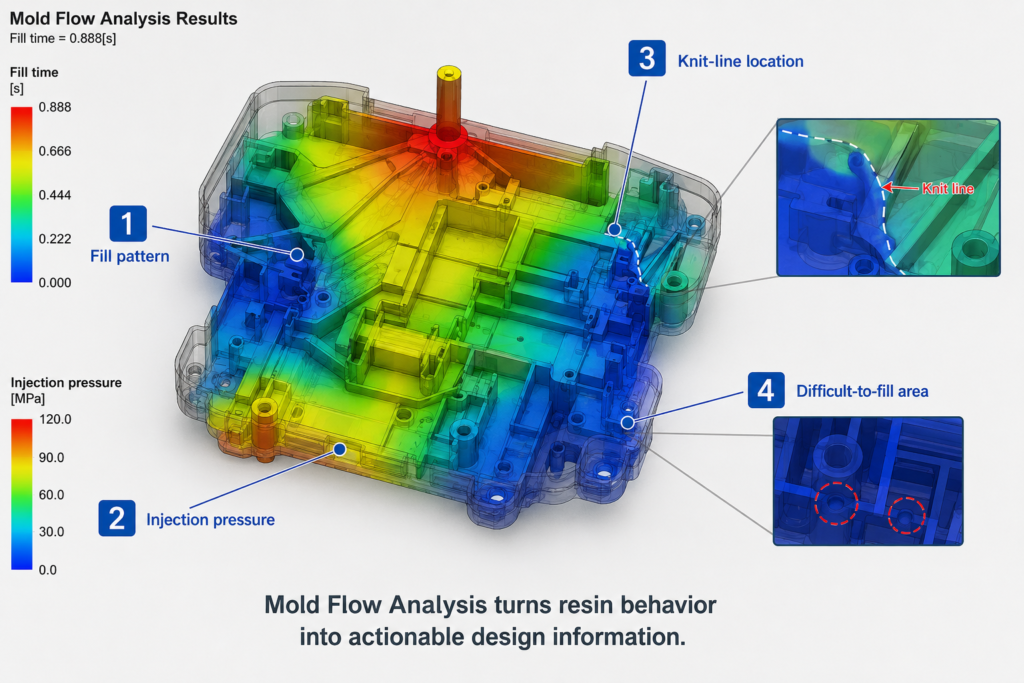
What Mold Flow Analysis Actually Shows
Mold Flow Analysis digitally simulates how resin fills the cavity.
For injection molding engineers, several outputs are particularly useful.
1. Fill Pattern
The fill pattern shows how the resin moves through the part.
It helps identify:
- Long flow paths
- Unbalanced filling
- Hesitation areas
- Difficult-to-fill features
This is often the first result engineers review.
2. Injection Pressure
The analysis can show how much pressure is required to fill the cavity.
Increasing pressure is not always a solution.
Excessive pressure can increase the risk of:
- Flash
- Parting-line problems
- Mold stress
- Dimensional variation
It may also indicate that the geometry, gate location, or material needs to be reconsidered.
3. Knit-Line Location
When the flow splits around a hole, boss, insert, or other obstruction, separate flow fronts eventually meet.
That meeting point creates a potential knit line.
The key question is not necessarily:
“Can we eliminate the knit line?”
A better question is:
“Where will the knit line occur, and is that location acceptable?”
A knit line on a hidden, low-stress surface may be acceptable.
The same knit line through a structural snap feature may require a design change.
4. Difficult-to-Fill Areas
Mold Flow can highlight areas where the resin struggles to reach the end of the cavity.
These areas often correspond to:
- Thin walls
- Long flow paths
- Deep features
- Sharp changes in geometry
This information can be used before tooling to determine whether a geometry modification is necessary.
Engineering Reference Data: When Is Mold Flow Worthwhile?
Not every molded part requires a detailed simulation.
For a simple, relatively thick component with a straightforward gate, experienced mold engineers may be able to predict filling behavior through conventional DFM review.
Mold Flow becomes increasingly valuable when several risk factors appear together.
| Design Condition | Simulation Value |
|---|---|
| Simple geometry | Lower |
| Thin-wall geometry | High |
| Long flow length | High |
| Multiple gates | High |
| Large cosmetic housing | High |
| Complex internal features | High |
| Difficult-flowing resin | High |
| Glass-filled material | High |
| Tight dimensional requirements | Very High |
This is particularly important for expensive or complex tooling.
The more difficult it is to modify the mold later, the more valuable it is to understand the filling behavior beforehand.
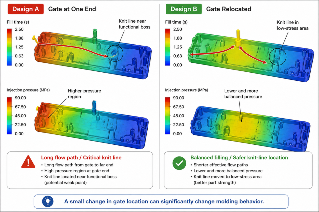
Gate Location: One of the Most Important Variables
Gate location has a direct effect on the entire filling pattern.
Changing the gate can change:
- Flow length
- Filling pressure
- Knit-line location
- Air-trap location
- Flow balance
- Fiber orientation
For this reason, gate selection should not be based solely on:
- Ease of machining
- Gate appearance
- Automatic degating
The gate is effectively the starting point of the molding process.
Its position can determine what happens throughout the rest of the cavity.
Using Mold Flow to Evaluate Wall Thickness
Wall thickness has a direct influence on resin flow.
As a section becomes thinner:
- Flow resistance increases
- The material cools more quickly
- Filling becomes more difficult
- Required pressure can increase
This does not mean that the solution is always to increase wall thickness.
A better engineering approach is to evaluate several options:
- Increase local wall thickness
- Move the gate
- Shorten the flow path
- Add another gate
- Modify the geometry
- Select a different resin
Mold Flow allows these alternatives to be compared before committing to tooling.
Material Selection Is Part of the Flow Analysis
Material selection should not be treated as a separate step from mold design.
Different resins have different:
- Viscosity
- Processing temperatures
- Shrinkage behavior
- Flow characteristics
- Cooling behavior
A part that fills easily in PP may require a very different approach when molded in PC or a glass-filled engineering resin.
For critical components, the actual resin grade should therefore be confirmed before relying on simulation results.
A simulation performed with the wrong material can lead engineers toward the wrong conclusion.
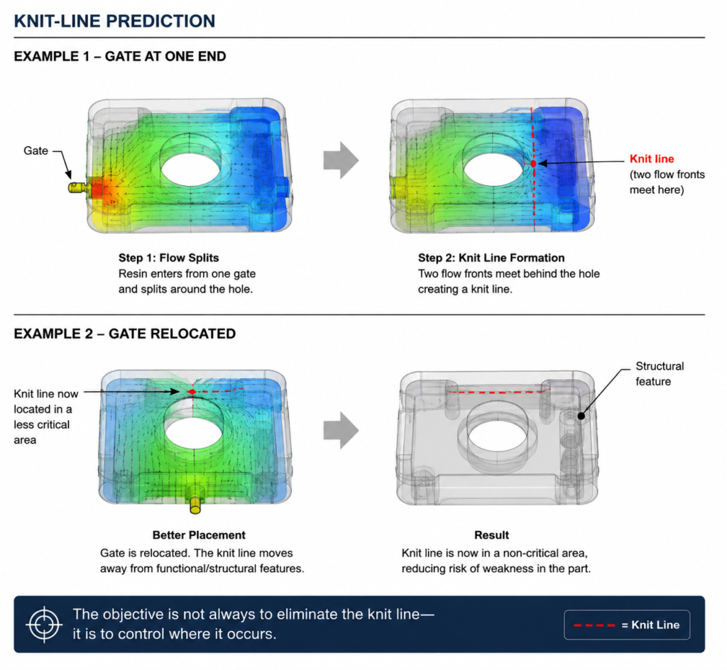
Mold Flow and Knit Lines
Mold Flow is particularly useful when the geometry contains flow interruptions.
Consider a hole in a molded housing.
The resin flows around both sides of the hole and then reconnects.
That location becomes a potential knit line.
The simulation can show whether the resulting knit line is:
- Hidden
- Cosmetic
- Structural
- Located near a fastening point
- Located near a snap feature
This gives the designer an opportunity to change the design before the mold is manufactured.
Mold Flow and Air Traps
Air must escape as plastic enters the cavity.
If the final filling area has no effective escape path, air can become trapped.
Typical locations include:
- Ends of flow paths
- Deep pockets
- Blind cavities
- Areas behind ribs
- Complex corners
Potential results include:
- Burn marks
- Short shots
- Poor surface quality
- Local weakness
Mold Flow can help predict these locations before the mold is built.
The mold engineer can then evaluate:
- Vent locations
- Gate changes
- Geometry modifications
- Ejection-side venting
[Engineering Illustration 4: Air Trap Prediction]
Image requirements:
Create a three-stage injection molding sequence:
Stage 1:
Resin enters the cavity and begins filling.
Stage 2:
The flow front pushes air toward the last-to-fill region.
Stage 3:
Air becomes trapped because there is no effective venting path.
Clearly highlight the predicted air-trap location.
Suggested caption:
“Every filling process also requires a controlled path for displaced air to escape.”
Mold Engineering Perspective
Mold Flow Analysis should not be treated as an automatic design decision.
The software identifies potential problems.
The engineer decides what to do about them.
For example:
High Injection Pressure
Possible solutions:
- Modify wall thickness
- Relocate the gate
- Add another gate
- Reduce flow length
- Consider a different resin
Knit Line in a Critical Area
Possible solutions:
- Change gate location
- Modify the feature
- Change the number of gates
- Evaluate another material
Difficult-to-Fill Area
Possible solutions:
- Increase local thickness
- Improve flow balance
- Shorten the flow path
- Adjust the processing window
Air Trap
Possible solutions:
- Add or relocate vents
- Change gate location
- Modify local geometry
The simulation provides evidence.
Engineering judgment provides the solution.
Simulation Is Not a Substitute for Mold Trials
A Mold Flow result is a prediction, not a guarantee.
Actual molding can still be affected by:
- Actual resin batch
- Moisture content
- Machine characteristics
- Mold temperature
- Injection speed
- Cooling performance
- Tool manufacturing variation
For this reason, the most effective workflow is:
Part Design → DFM Review → Mold Flow → Mold Design → Tooling → Trial → Measurement → Process Optimization
Mold Flow reduces uncertainty.
It does not eliminate the need for physical validation.
Common Mold Flow Mistakes
1. Running Analysis Too Late
If the mold design is already finalized, many design options have disappeared.
The greatest value comes before steel is cut.
2. Using the Wrong Material
Simulation results depend heavily on resin properties.
3. Looking Only at Fill Time
A good fill pattern does not automatically mean a good molded part.
Pressure, knit lines, air traps, and temperature behavior should also be reviewed.
4. Treating Every Result as a Failure
A predicted knit line is not automatically a defect.
Its location and function matter.
5. Ignoring Gate Strategy
Gate location is one of the most powerful variables available to the mold engineer.
DFM Quick Review Checklist: Mold Flow Analysis
- Confirm the actual resin grade before analysis.
- Review gate location and flow direction.
- Check injection pressure and difficult-to-fill areas.
- Review knit-line locations against functional features.
- Check predicted air traps and venting strategy.
- Use simulation results to compare design alternatives.
- Validate critical conclusions through mold trials and measurement.
Final Thoughts
Mold Flow Analysis is not about producing attractive simulation images.
Its real purpose is to answer difficult engineering questions before tooling begins:
Will the part fill?
Where will the flow fronts meet?
Where will air become trapped?
How much pressure will be required?
Is the gate in the right location?
Does the material work with the geometry?
These questions are much easier—and much cheaper—to answer before the mold is built.
Once steel has been cut, changing the gate, wall thickness, cooling system, or part geometry becomes considerably more expensive.
For complex and precision injection molded parts, Mold Flow Analysis is therefore best viewed as a pre-tooling risk reduction tool.
The best simulation is not the one with the most colorful results.
It is the one that helps an engineer make a better mold.