


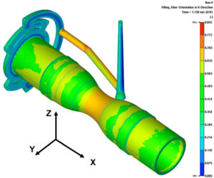
Why Glass-Filled Plastics Are More Difficult to Mold
Glass-filled plastics are widely used when a component needs greater stiffness, improved strength, better dimensional performance, or increased resistance to deformation compared with an unfilled polymer. Typical applications include structural housings, brackets, gears, connector components, automotive parts, and precision mechanical components. But there is an important engineering trade-off: adding glass fiber changes not only the properties of the finished plastic, but also how the material flows, shrinks, cools, and behaves inside the mold. A design that molds reliably in an unfilled resin may develop warpage, weaker weld lines, surface defects, or unexpected dimensional variation when converted to a glass-filled grade. The same gate location, wall thickness, and processing conditions may no longer produce the same result. These difficulties are closely related to fiber orientation. As the molten material flows through the runner, gate, and cavity, the fibers tend to align with the local flow pattern. That orientation influences mechanical properties and shrinkage, often differently in different directions. The engineering challenge is therefore not simply to make the material flow. It is to control the interaction between material properties, part geometry, mold design, and processing conditions. 1. What Are Glass-Filled Plastics? Glass-filled plastics are polymers reinforced with short or, in some applications, longer glass fibers. The fibers are incorporated into a resin to improve selected mechanical and dimensional properties. Common examples include: The glass content is often specified by weight, such as 15%, 30%, or 40% glass fiber. These figures describe the material composition, not a direct percentage increase in strength or stiffness. The behavior of a glass-filled grade depends on several variables: Two materials containing the same nominal glass percentage can behave differently because their base resins, fiber characteristics, and formulations differ. What does glass fiber actually change? Glass fibers are much stiffer than most unfilled thermoplastic matrices. When properly incorporated into a polymer, they can improve stiffness and strength under suitable loading conditions. They can also reduce shrinkage in certain directions and improve resistance to deformation under load or elevated temperature, depending on the material grade. However, these benefits are not uniform in every direction. A glass-filled component may be stiff along one direction but less stiff across it. Its shrinkage can also differ substantially between the flow direction and the direction perpendicular to flow. Engineering implication: Material selection must consider the actual grade and the direction of the expected loads, not just the words “glass-filled” on a material specification. 2. Why Fiber Orientation Changes Everything Fiber orientation is one of the most important factors in glass-filled injection molding. During filling, the molten polymer carries glass fibers through the runner, gate, and cavity. The flow field influences how the fibers align. Near some cavity walls, fibers tend to align with the flow direction; in other regions, they may orient differently because of fountain flow, shear, geometry, and changes in flow direction. The resulting orientation is not uniform throughout the part. A molded wall can contain different orientation patterns near its surface and core. Around a rib, boss, hole, or sudden change in section thickness, the local flow pattern may change significantly. Flow direction is not the same as fiber orientation everywhere Although fibers often align with the dominant flow direction, engineers should not assume that every fiber follows a single straight path. Fiber orientation is affected by: When the flow divides around a hole and then rejoins, for example, the orientation patterns on either side may differ. The region where the flows meet can become a weld line, with a local fiber arrangement that differs from the surrounding material. Why orientation matters to the finished component Fiber orientation influences: This explains why a glass-filled part may pass dimensional inspection in one direction but show unexpected variation in another. It also explains why simply increasing the glass content does not guarantee a better component. More reinforcement may improve certain properties while increasing directional differences and making the molding process more sensitive to geometry and flow. Suggested visual 1 — Diagram needed: A plastic wall showing a simplified fiber-orientation pattern through its thickness, with different orientation near the surface and core. Include an arrow for the main flow direction. Label the image as a conceptual illustration. 3. Glass-Filled Plastics Do Not Shrink Uniformly Shrinkage is a major reason glass-filled plastics can be difficult to control dimensionally. As a thermoplastic cools, its volume changes. Glass fibers influence that change because their thermal and mechanical behavior differs from the polymer matrix. In many short-glass-fiber thermoplastics, shrinkage is lower along the dominant fiber orientation than across it. The actual behavior depends on the polymer, fiber content, orientation, processing conditions, and measurement direction. This creates a key engineering issue: shrinkage becomes directional rather than uniform. Flow-direction shrinkage versus transverse shrinkage Consider a long molded bracket. If fibers align mainly along the length of the bracket, shrinkage along that direction may differ from shrinkage across its width. If the flow direction changes around a hole or branch, the shrinkage pattern may also change locally. The result can be a part that does not shrink uniformly, even when its wall thickness and nominal material grade appear consistent. Engineering factor Potential effect on a glass-filled part Fiber orientation Creates directional differences in shrinkage and mechanical properties Wall thickness Changes cooling behavior and the local flow pattern Gate location Influences how fibers align across the part Packing conditions Affect compensation for volumetric shrinkage Material moisture and processing history May affect flow, properties, and dimensional consistency, depending on the resin Mold temperature distribution Influences cooling and shrinkage development These factors interact. A dimensional problem should not automatically be attributed to the material alone. Why mold shrinkage compensation becomes more complicated For an unfilled material, engineers may be able to establish a relatively predictable shrinkage allowance for a given geometry and process. With glass-filled materials, a single shrinkage value may be insufficient for complex components. Different directions and regions can behave differently, especially where the flow field changes. This does not mean glass-filled materials cannot achieve tight tolerances. It means

Your CAD Model Looks Perfect. So Why Can’t We Build the Mold?
Why Your CAD Model Looks Fine but Is Not Moldable A CAD model can look completely finished. The geometry is clean. The surfaces are continuous. The assembly works. The product looks exactly the way the designer intended. Then the tooling engineer opens the file and starts asking questions: Where is the parting line? How will this feature be ejected? What is the mold opening direction? Where can the gate go? How will the core be machined? How will the mold cool this area? What happens to this dimension after shrinkage? Suddenly, the “finished” CAD model doesn’t look quite so finished. This is a common gap between product design and injection molding. A CAD model describes what you want to make. A moldable design also needs to consider how you are going to make it. Here are some of the most common reasons why a perfectly good-looking CAD model can still be difficult—or even impractical—to mold. 01 — Draft Angle Was Never Considered One of the most basic injection molding requirements is also one of the most frequently overlooked during product design: Draft. A vertical wall may look perfectly acceptable in CAD. But during mold opening, the molded part has to separate from the mold surface. Without sufficient draft, the part can experience: The required draft depends on factors such as material, surface texture, depth, geometry, and tooling conditions. This means draft is not simply a number added at the end of the design process. It is part of the relationship between: Part geometry → Mold surface → Ejection 02 — The Part Has No Practical Parting Strategy A CAD model may contain all the required geometry but still have no sensible way to divide the mold. Every injection molded part needs a practical relationship between: Core + Cavity + Parting Line The parting line affects: Moving the parting line by a few millimeters can sometimes completely change the mold concept. This is why parting-line strategy should be discussed during product design—not after the tooling supplier receives the final CAD file. The question is not only whether the geometry can be modeled. It is whether the geometry can be separated from the mold. 03 — Hidden Undercuts Are Everywhere Undercuts are one of the classic reasons why a part that looks simple in CAD can become complicated in tooling. They can appear in: The tooling engineer may then need to consider: Sometimes the additional tooling mechanism is completely justified. Sometimes a small product-design change can eliminate the mechanism entirely. For example, changing the direction of a feature or adjusting its geometry may turn a complicated slide into a simple mold feature. That is why DFM is not about telling designers: “You cannot do this.” It is about asking: “What is the most practical way to manufacture what you need?” 04 — Wall Thickness Looks Fine in CAD—but Not in Flow Uniform wall thickness is often discussed as a basic injection molding rule. But the real issue is more complicated. A part may look perfectly reasonable in CAD while containing: These areas can affect how molten plastic fills and cools. Potential consequences include: This is where simulation can become useful. A Mold Flow analysis can help engineers understand whether the geometry is likely to create filling, packing, cooling, or warpage problems before steel is cut. 05 — Ribs and Bosses Were Designed Without Tooling in Mind Ribs and bosses are essential features in many plastic products. They provide: But they also create manufacturing considerations. A deep boss may require a difficult core. A thick rib can create sink marks. A narrow gap may be difficult to machine or polish. A boss positioned too close to another feature can create tooling or cooling problems. The question should therefore not simply be: “Can this feature be created in CAD?” It should be: “Can this feature be molded, cooled, ejected, inspected and maintained?” 06 — The Gate Has Nowhere Good to Go Product designers naturally focus on the finished component. Tooling engineers have another question: Where does the plastic enter? Gate location can influence: A CAD model may look excellent while leaving no practical gate location. The gate may need to be placed on a cosmetic surface. Or the flow length may become excessive. Or a weld line may appear near a critical feature. Sometimes the best solution is not simply changing the mold. It may be changing the product geometry. Gate strategy is often a product-engineering decision as much as a tooling decision. 07 — Ejection Was Treated as Someone Else’s Problem A mold does not simply create a part. It also has to release it. The tooling engineer therefore needs to understand: How will the molded component leave the mold? Ejection may involve: The location and geometry of these systems can affect the part. For example, an ejector pin may leave a mark on a visible surface. A thin wall may not tolerate a high local ejection force. A deep rib may make ejection difficult. A cosmetic housing may have very limited areas where ejector marks are acceptable. If the ejection strategy is discovered too late, the available options become much smaller. 08 — Cooling Has Not Been Considered Cooling is one of the most important—and often least visible—parts of injection molding. A CAD model may contain beautiful external geometry. But if the mold cannot cool the part effectively, production can still become difficult. Uneven cooling can contribute to: This becomes particularly important for: A production-ready design therefore needs to consider not only how plastic flows into the cavity, but also how heat will leave the molded part. 09 — Critical Dimensions Are Not Connected to the Mold Strategy A drawing may specify a very tight tolerance. For example: ±0.03 mm But specifying the tolerance is only the beginning. The engineering team should also understand: A critical dimension should therefore be connected to a manufacturing strategy. Otherwise, the drawing may simply demand a result without defining a realistic path to achieve it.
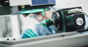
A Medical Plastic Part Can Be Dimensionally Perfect and Still Fail.
Why is dimensional accuracy not enough for medical plastic components? Explore material, surface quality, flash, weld lines, cleanliness, validation and process consistency.