


What Can Mold Flow Actually Tell an Injection Mold Engineer?
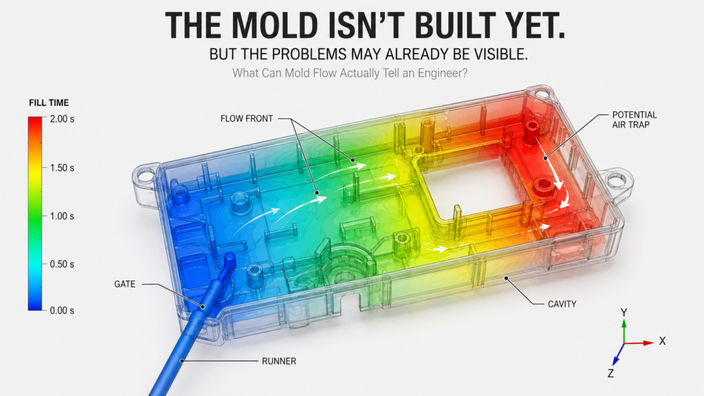
The mold has not been machined yet.
The steel has not been cut.
The first trial has not even been scheduled.
And yet, an experienced tooling engineer may already be able to see where potential molding problems are likely to occur.
That is where Mold Flow Analysis becomes valuable.
Mold Flow is often described simply as a way to simulate how plastic flows through a mold. But for an injection mold engineer, that definition is too narrow.
The real question is not:
“How will the plastic flow?”
It is:
“If we build the mold with this gate location, this wall thickness, this material, and this process window, what is likely to happen?”
That is the real value of Mold Flow.
It gives engineers an opportunity to identify potential problems before those problems become steel.
01 — Fill Pattern: Where Will the Plastic Actually Go?
The first question is simple:
How will the melt front move through the cavity?
When resin enters through the gate, the flow does not always progress evenly.
A complex injection molded component may contain:
- Thin-wall sections
- Deep ribs
- Bosses
- Openings
- Different wall thicknesses
- Long flow paths
These features can cause the flow front to hesitate, split, accelerate, or meet again.
Mold Flow can visualize the filling sequence and help engineers evaluate whether the current gate location and flow strategy are appropriate.
If the filling pattern is significantly unbalanced, other problems may follow:
- Short shot
- Higher injection pressure
- Weld lines
- Air traps
- Uneven cooling
- Warpage
So Fill Pattern is not simply an animation showing plastic moving through a cavity.
It is one of the first ways to validate the gate and flow strategy.
02 — Injection Pressure: Can the Machine Actually Fill the Part?
A part may look simple in CAD and still be difficult to fill.
Injection pressure is influenced by several factors, including:
- Flow length
- Wall thickness
- Resin viscosity
- Melt temperature
- Mold temperature
- Gate and runner restrictions
- Part geometry
A long, thin flow path can create significant resistance.
If the required injection pressure approaches the practical limits of the molding machine, the engineering team has several options.
Increasing injection pressure is one possibility.
But it is not always the best answer.
Sometimes the better solution is to:
- Move the gate
- Add or relocate a gate
- Modify the wall thickness
- Improve the runner design
- Adjust the material or grade
- Optimize the process window
This is why Mold Flow should not be used simply to report a number such as:
Injection Pressure = 120 MPa
The more important question is:
Why is the pressure this high, and what can we change before the mold is built?
03 — Weld Lines: Where Will Two Flow Fronts Meet?
Weld lines are a classic example of why gate location matters.
Imagine a plastic housing with a central opening.
The melt enters from one side and splits into two flow fronts.
The two fronts travel around the opening and eventually meet again.
That meeting point creates a weld line.
The question is not simply:
“Will there be a weld line?”
For many injection molded components, weld lines are unavoidable.
The more important questions are:
Where will the weld line be?
And:
What is located at that position?
A weld line on a non-critical cosmetic area may be acceptable.
A weld line across a:
- Structural boss
- Snap-fit
- Sealing surface
- High-stress area
- Functional feature
may be much more serious.
Mold Flow allows engineers to evaluate the predicted weld-line location and determine whether the gate strategy should be changed.
Sometimes moving the weld line is more effective than trying to eliminate it completely.
The goal is not always to eliminate the weld line. The goal is to put it where it does the least harm.
04 — Air Traps: Where Will the Air Go?
There is something inside every empty mold cavity before injection starts:
Air.
As molten plastic fills the cavity, that air needs somewhere to escape.
If it cannot escape efficiently, it may become trapped at the end of a flow path or inside a deep feature.
This can result in:
- Air traps
- Burn marks
- Short shots
- Gas-related defects
- Localized pressure problems
Mold Flow can help predict where flow fronts are likely to converge and where air may become trapped.
That information can then be used to review the venting strategy.
Potential solutions may include:
- Parting-line vents
- Ejector vents
- Insert vents
- Additional venting features
- Vacuum venting for specialized applications
The important point is:
Mold Flow does not only tell you where the plastic will go. It can also help you understand where the air will end up.
05 — Cooling and Warpage: Why Does the Part Come Out Distorted?
A part can be completely filled and still fail dimensional inspection.
Why?
Because filling is only part of the molding process.
Warpage can be influenced by:
- Differential shrinkage
- Cooling imbalance
- Fiber orientation
- Residual stress
- Wall-thickness variation
- Gate location
- Material behavior
For example, if one region of the mold cools significantly faster than another, the resulting shrinkage can become unbalanced.
With glass-filled materials, fiber orientation adds another layer of complexity because the material may shrink differently in different directions.
Mold Flow can help engineers understand these relationships before production begins.
This means warpage does not always have to be treated as a problem discovered during molding trials.
Some of its causes can be addressed at the product and tooling design stage.
06 — Fiber Orientation: Where Are the Fibers Going?
This becomes particularly important when molding reinforced engineering plastics such as:
- PA66 GF
- PBT GF
- PPS GF
- PEEK GF
- Carbon-fiber reinforced materials
The fibers do not simply distribute randomly throughout the part.
They tend to orient according to the flow.
That orientation can affect:
- Mechanical strength
- Shrinkage
- Warpage
- Dimensional stability
- Anisotropic behavior
For applications such as automotive components, electrical connectors, motor components, and structural parts, this can be critical.
So Mold Flow is not only answering:
“Will the cavity fill?”
It can also help engineers understand:
“What is happening inside the material while it fills?”
07 — What Should Engineers Actually Look For?
A Mold Flow report can contain a lot of colorful images, contours, and numerical results.
But a good analysis should lead to better engineering decisions.
Instead of asking:
“Does the simulation look good?”
Engineers should ask:
Is the gate location appropriate?
Does the gate create a reasonable filling pattern and place potential weld lines away from critical features?
Is the filling balanced?
Are there areas that may hesitate, fill late, or require excessive pressure?
Is the injection pressure acceptable?
Can the selected machine and process window realistically fill the part?
Where are the critical weld lines?
Are they located on structural, sealing, cosmetic, or high-stress areas?
Where will air become trapped?
Does the mold design provide an effective venting path?
Is the cooling strategy balanced?
Could temperature differences lead to excessive shrinkage or warpage?
Could fiber orientation affect performance?
Is the material orientation consistent with the functional requirements of the component?
Is the predicted warpage acceptable?
If not, can the problem still be addressed through product design, gate location, cooling, or process changes?
And finally:
What can we still change before the mold is built?
That is often the most important question of all.
08 — The Real Value of Mold Flow
Once steel has been machined, design changes become more expensive.
A problem discovered during T1 may require:
- Mold modification
- EDM work
- Welding
- Grinding
- Polishing
- Insert replacement
- Additional molding trials
- Additional validation time
Mold Flow cannot eliminate every molding problem.
It cannot replace engineering judgment.
And it should not be treated as a guarantee that the first trial will be perfect.
Its real value is different.
It allows the engineering team to move part of the learning process forward in time.
Instead of:
Build → Trial → Find Problem → Modify → Trial Again
the goal becomes:
Predict → Analyze → Design → Build → Validate
That does not mean every issue can be predicted perfectly.
It means the team has a better opportunity to identify avoidable risks while there is still time to change the design.
The Bottom Line
Mold Flow is not just a colorful simulation.
It is a way to understand how:
Material behavior → Product design → Mold design → Process conditions → Part quality
are connected.
The best time to solve a molding problem is not after T1.
It is not after the first dimensional report.
And it is certainly not after several rounds of mold modification.
The best time is before the mold is built.
That is what Mold Flow gives engineers:
Not a perfect prediction.
But an opportunity to see potential problems earlier—and make better tooling decisions while there is still time to change them.
The mold isn’t built yet.
But the problems may already be visible.