


A part can have the right wall thickness, sufficient draft, and a well-designed gate—and still create an ejection problem if the core and cavity are positioned incorrectly.
Core and cavity placement is one of the fundamental decisions in mold design.
It determines:
- Which mold half forms each surface
- Where the part will shrink
- Which side will retain the part
- Where ejector pins can act
- How features such as holes, ribs, and tabs should be drafted
The basic objective is simple:
When the mold opens, the molded part should remain on the side where the ejection system can remove it safely.
This sounds straightforward. In complex parts, however, shrinkage, draft, texture, and feature geometry can make the result much less predictable.
Engineering Problem
An injection mold normally has two primary halves:
- A-side / cavity side
- B-side / core side
The A-side is generally the stationary side of the mold, while the B-side moves with the machine and contains the ejector system.
During molding, the resin fills the cavity and cools.
As the plastic shrinks, it may:
- Pull away from one mold surface
- Grip another surface
- Lock around cores or features
This creates a critical engineering question:
Which side will the part stay on when the mold opens?
If the part remains on the B-side, ejector pins can push it away from the core.
If it unexpectedly remains on the A-side, there may be no effective mechanism to remove it.
That can lead to:
- Sticking
- Part deformation
- Broken features
- Difficult automatic production
- Additional tooling complexity
The original Protolabs guidance emphasizes that the part should remain with the mold half containing the ejector system, and uses a cup-shaped part to illustrate how shrinkage and core placement determine which side retains the part.
Root Cause: Shrinkage Determines Where the Part Wants to Stay
The most important concept is shrinkage.
Consider a simple plastic cup.
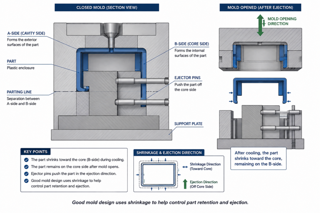
If the outside of the cup is formed by the cavity and the inside is formed by a core, the plastic will generally shrink toward the core as it cools.
This is useful.
When the mold opens:
- The exterior releases from the cavity
- The part remains around the core
- Ejector pins can push the cup off the core
The mold is effectively using shrinkage to assist ejection.
Reverse the arrangement, however, and the part may remain on the wrong side of the mold.
This is why core and cavity placement should be considered during part design—not after the mold structure has already been determined.
Engineering Reference Data
Unlike draft angle or wall thickness, there is no universal “correct” numerical value for core/cavity placement.
The decision is primarily geometric.
During DFM review, engineers should evaluate:
| Design Factor | Effect on Mold Design |
|---|---|
| Part shrinkage | Determines likely mold-side retention |
| Draft angle | Controls release direction |
| Surface texture | Can increase mold adhesion |
| Deep internal features | Often favor core-side retention |
| Ribs and bosses | May influence ejection force |
| Through-holes | Require careful core orientation |
| Tabs and thin projections | Can deform during mold opening |
| Cosmetic surfaces | May require controlled cavity release |
The key principle is:
The mold should be designed so that shrinkage, draft, and ejection work in the same direction.
Core vs. Cavity: The Basic Arrangement
For a typical enclosure, the most straightforward arrangement is often:
- Exterior surfaces → cavity / A-side
- Interior surfaces → core / B-side
- Ejection → B-side
This arrangement allows the molded part to shrink onto the core while releasing from the cavity.
It also provides a practical location for ejector pins.
However, this is a starting point—not an automatic rule.
Complex geometry can require a different strategy.
Why the Ejection Side Matters
The B-side normally contains:
- Ejector pins
- Ejector plates
- Ejector sleeves
- Other ejection mechanisms
Therefore, the part should ideally remain on this side after mold opening.
This sounds obvious, but part geometry can work against it.
For example, a textured exterior surface may grip the cavity.
A deep internal feature may grip the core.
A poorly oriented hole may cause a small core to retain the part on the wrong side.
The mold engineer therefore needs to balance the retention forces.
Core and Cavity Placement for Enclosures
Enclosures are one of the most common applications where this decision becomes important.
Consider a rectangular electronic housing with:
- Four through-holes
- Internal ribs
- Mounting bosses
- Snap features
The basic housing may be easy to mold.
The problem often comes from the secondary features.
A through-hole can be formed by a core pin.
The direction of that core pin matters.
If the core pin is oriented toward the wrong mold half, the part may remain on the cavity side after opening.
A better design often directs the feature so that the core is associated with the ejector side.
[Engineering Illustration 2: Correct vs. Incorrect Core Placement for a Housing]
Image requirements:
Show the same rectangular enclosure in two side-by-side mold designs.
Design A — Higher Ejection Risk
- Hole core positioned toward the cavity side
- Part tends to remain on A-side
- No direct ejector support
- Highlight the retention problem
Label:
“Core pulls against the ejection strategy”
Design B — Preferred Arrangement
- Hole core positioned toward the B-side
- Part remains on ejector side
- Ejector pins support the molded part
Label:
“Core direction aligned with ejection”
Add an arrow showing the mold opening direction.
Draft Direction Is Part of Core and Cavity Design
Draft is not only about reducing friction.
It also helps determine which mold surface releases first.
For features that should remain on the B-side, the draft direction should generally encourage release from the A-side and retention around the B-side core.
This becomes particularly important for:
- Internal ribs
- Tabs
- Strips
- Bosses
- Core pins
- Features spanning openings
Poor draft direction can create a situation where the part wants to remain on the wrong mold half.
Deep Ribs and Internal Features
Deep internal ribs can create another challenge.
There are two fundamentally different approaches to forming an internal wall.
Approach A: Deep Pocket Machining
The mold steel is machined deeply into one side of the mold.
Approach B: Core Formation
A projecting core forms the interior geometry.
The second approach can often provide a more natural ejection strategy because the molded part shrinks around the core and can then be pushed off by ejector pins.
The correct choice depends on:
- Geometry
- Depth
- Draft
- Mold construction
- Machining access
- Ejection requirements
[Engineering Illustration 3: Deep Pocket vs. Core Formation]
Image requirements:
Create a side-by-side cross-sectional comparison.
Left: Deep Pocket
- Show a deep cavity machined into mold steel
- Highlight difficult machining access
- Show potential ejection concerns
Right: Core Formation
- Show a projecting core forming the internal wall
- Show the molded part shrinking around the core
- Show ejector pins pushing the part away
Caption:
“The same part geometry can require very different mold strategies.”
Surface Texture Can Change the Retention Strategy
Surface finish should also be considered.
A polished surface generally releases more easily than a textured surface.
Texture creates microscopic mechanical engagement between the mold and plastic.
As a result, a heavily textured exterior surface may remain attached to the cavity longer than expected.
This can interfere with the intended ejection strategy.
For textured parts, engineers should therefore review:
- Texture depth
- Draft angle
- Shrink direction
- Ejection force
- Cosmetic requirements
A surface that looks acceptable in CAD may behave very differently once texture is applied.
Mold Engineering Perspective
Experienced mold engineers do not simply divide a part into:
A-side = outside
B-side = inside
They evaluate the entire retention and ejection system.
The real question is:
When the mold opens, what forces determine where the part stays?
Those forces may include:
- Plastic shrinkage
- Surface texture
- Draft
- Core friction
- Feature geometry
- Ejector force
- Part stiffness
The objective is to make these forces work together.
A good design creates a predictable sequence:
Mold opens → part releases from cavity → part remains on core → ejectors push part off core
That sequence is much easier to automate and repeat.
Common Core and Cavity Design Mistakes
1. Choosing the Parting Line Before Considering Ejection
The most visually convenient parting line is not always the best engineering solution.
2. Ignoring Shrink Direction
Plastic shrinkage can determine which mold surface retains the part.
3. Incorrect Core Direction
Through-holes and internal features can accidentally pull the part toward the wrong mold half.
4. Ignoring Texture
Texture can significantly increase surface retention.
5. Designing Features Without Mold Opening Direction
Tabs, ribs, bosses, and projections should be evaluated according to the actual mold pull direction.
DFM Quick Review Checklist: Core and Cavity Placement
- Is the intended parting line compatible with ejection?
- Will the part remain on the ejector side after mold opening?
- Do shrinkage and draft support the intended retention direction?
- Are core pins and internal features oriented correctly?
- Have texture and cosmetic surfaces been considered?
- Can ejector pins support the part without deformation?
- Has the mold opening sequence been reviewed in 3D?
Final Thoughts
Core and cavity placement is not simply a mold construction decision.
It is a part-design decision.
A well-designed component should naturally move through the intended molding sequence:
Fill → Cool → Shrink → Release → Eject
When the geometry, draft, shrinkage, core direction, and ejection system all work together, the mold can release the part predictably with minimal force.
When they work against each other, even a relatively simple component can become difficult to manufacture.
For precision injection molding, the best time to solve a core-and-cavity problem is before the mold is built.