


Many plastic parts look perfect in CAD but become difficult to manufacture once they enter the injection molding stage.
One of the most common reasons is the lack of proper draft angle.
Draft angle is the slight taper applied to vertical surfaces of a molded part, allowing the part to release smoothly from the mold.
Without sufficient draft, manufacturers may encounter:
- Parts sticking in the mold
- Scratches and drag marks
- Higher ejection force
- Mold surface damage
- Reduced production stability
For injection molding, draft is not a cosmetic adjustment.
It is a fundamental requirement for reliable mold operation.
Root Cause: Plastic Shrinkage Creates Friction Against the Mold
During injection molding, molten plastic fills the cavity and cools under pressure.
As the material cools:
- The plastic shrinks around the mold core.
- The part grips the steel surface.
- Ejection requires the part to slide away from the mold.
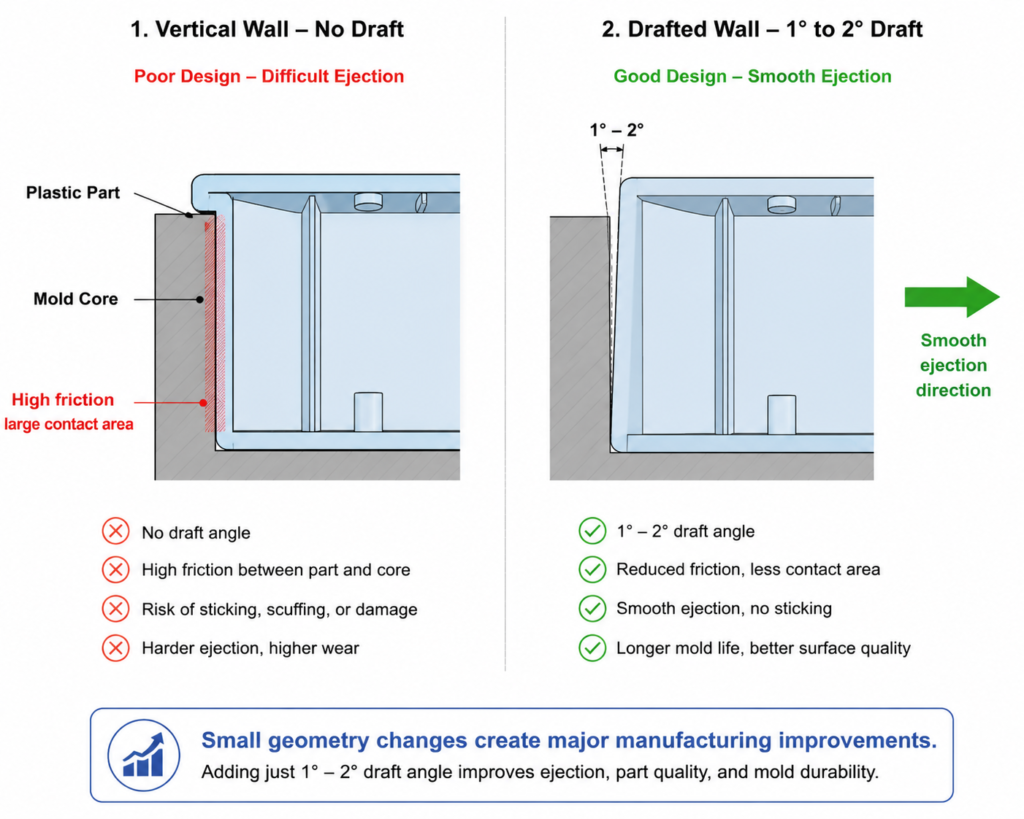
When a wall has zero draft, the entire surface remains in contact during ejection.
This creates:
- Higher friction
- Increased release force
- Surface damage risk
A small draft angle changes the release condition completely.
Instead of sliding against the mold surface, the part gradually separates from the steel.
Engineering Reference Data
Recommended Draft Angle Guidelines
The ideal draft angle depends on:
- Material shrinkage
- Part depth
- Surface texture
- Mold finish
- Ejection method
General recommendations:
| Surface Condition | Recommended Draft |
|---|---|
| Smooth surface | 0.5°–1° |
| Standard molded surface | 1°–2° |
| Textured surface | 2°–3° |
| Heavy texture | 3°–5° |
For most injection molded parts:
1° draft per side is a practical starting point.
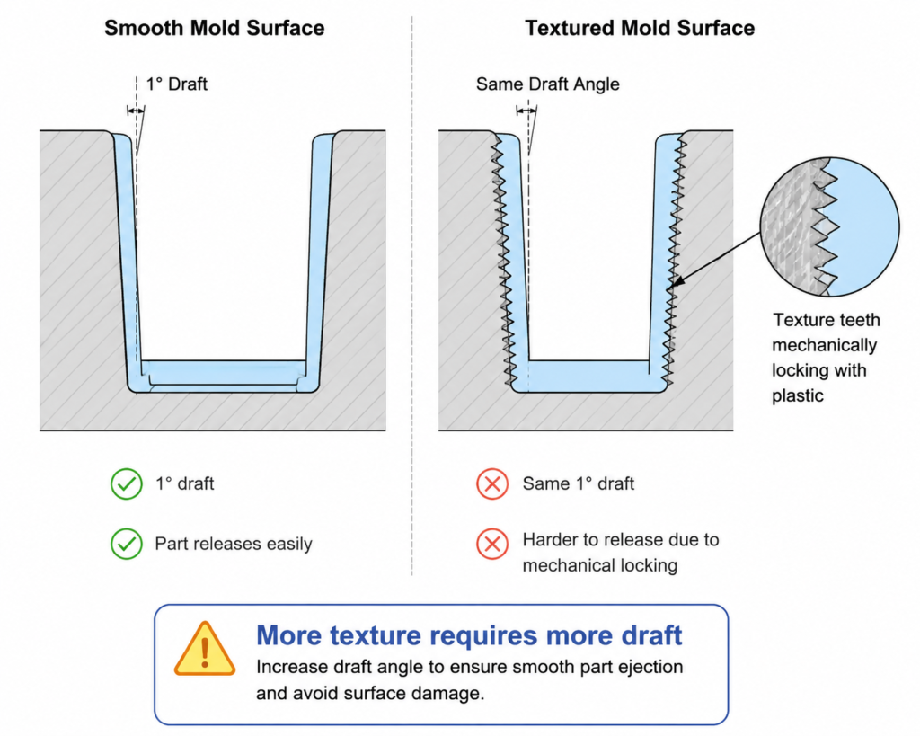
Draft Angle and Surface Texture
Texture is one of the most overlooked factors affecting draft.
A textured surface is not perfectly flat.
The microscopic peaks and valleys create mechanical resistance during ejection.
For example:
A polished surface may release with 1° draft.
A textured surface may require 3° or more.
General rule:
The deeper the texture, the more draft is required.
Draft Design Example: Plastic Housings
Electronic housings and covers are common applications where draft problems occur.
A typical mistake:
Designers create perfectly vertical walls because they look clean in CAD.
However, during molding:
- Core side friction increases
- Ejection force rises
- Cosmetic surfaces may be damaged
A better approach is to slightly taper the walls while maintaining functional dimensions.
Mold Engineering Perspective
When reviewing a part design, mold engineers usually ask:
“How will this surface release from the steel?”
not:
“Does this surface look correct in CAD?”
Every vertical surface affects:
- Mold opening
- Ejection force
- Tool polishing
- Surface quality
- Mold lifetime
Draft should be considered before tooling starts.
Adding draft after mold construction may affect:
- Critical dimensions
- Assembly fit
- Cosmetic requirements
Early consideration always reduces engineering risk.
Common Draft Design Mistakes
1. Designing Parts Like Machined Components
CNC machining and 3D printing allow vertical walls.
Injection molding does not.
2. Adding Texture Without Increasing Draft
Texture increases surface resistance and requires additional taper.
3. Forgetting Internal Features
Many designs include draft on external walls but ignore:
- Bosses
- Ribs
- Internal cavities
These areas also need proper release.
4. Assuming Small Parts Do Not Need Draft
Even small components experience shrinkage and ejection forces.
DFM Quick Review Checklist: Draft Angle
✓ All vertical surfaces have sufficient draft
✓ Texture depth has been considered
✓ Internal walls, ribs, and bosses include draft
✓ Ejection direction is clearly defined
✓ Cosmetic surfaces are protected from drag marks
✓ Draft requirements are reviewed before tooling begins
Final Thoughts
Draft angle is one of the smallest design details in injection molding.
However, it has a major influence on:
- Part release
- Surface quality
- Mold durability
- Production efficiency
A well-designed molded part does not fight the mold.
It works together with the mold.
Adding a few degrees of draft during product design can prevent weeks of tooling problems later.
For injection molding, draft is not a limitation.
It is a design advantage.