

Why Your CAD Model Looks Fine but Is Not Moldable
A CAD model can look completely finished.
The geometry is clean.
The surfaces are continuous.
The assembly works.
The product looks exactly the way the designer intended.
Then the tooling engineer opens the file and starts asking questions:
Where is the parting line?
How will this feature be ejected?
What is the mold opening direction?
Where can the gate go?
How will the core be machined?
How will the mold cool this area?
What happens to this dimension after shrinkage?
Suddenly, the “finished” CAD model doesn’t look quite so finished.
This is a common gap between product design and injection molding.
A CAD model describes what you want to make. A moldable design also needs to consider how you are going to make it.
Here are some of the most common reasons why a perfectly good-looking CAD model can still be difficult—or even impractical—to mold.
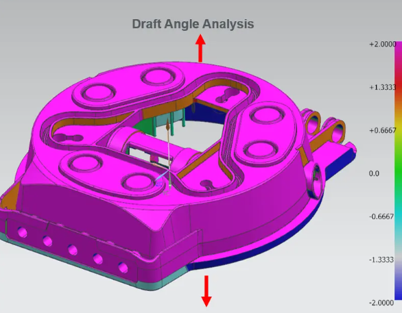
01 — Draft Angle Was Never Considered
One of the most basic injection molding requirements is also one of the most frequently overlooked during product design:
Draft.
A vertical wall may look perfectly acceptable in CAD.
But during mold opening, the molded part has to separate from the mold surface.
Without sufficient draft, the part can experience:
- Sticking
- Drag marks
- Surface damage
- Difficult ejection
- Excessive ejection force
The required draft depends on factors such as material, surface texture, depth, geometry, and tooling conditions.
This means draft is not simply a number added at the end of the design process.
It is part of the relationship between:
Part geometry → Mold surface → Ejection
02 — The Part Has No Practical Parting Strategy
A CAD model may contain all the required geometry but still have no sensible way to divide the mold.
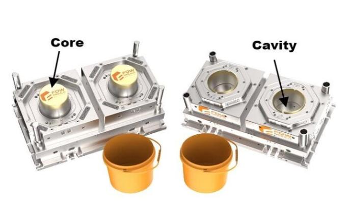
Every injection molded part needs a practical relationship between:
Core + Cavity + Parting Line
The parting line affects:
- Flash
- Cosmetic surfaces
- Dimensional control
- Tool complexity
- Ejection
- Machining
- Maintenance
Moving the parting line by a few millimeters can sometimes completely change the mold concept.
This is why parting-line strategy should be discussed during product design—not after the tooling supplier receives the final CAD file.
The question is not only whether the geometry can be modeled. It is whether the geometry can be separated from the mold.
03 — Hidden Undercuts Are Everywhere
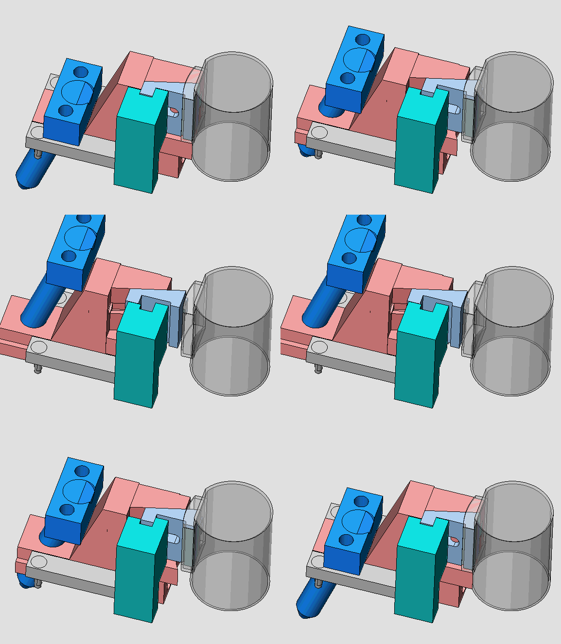
Undercuts are one of the classic reasons why a part that looks simple in CAD can become complicated in tooling.
They can appear in:
- Side holes
- Internal hooks
- Snap-fits
- Reverse surfaces
- Internal ribs
- Connector features
- Retaining features
The tooling engineer may then need to consider:
- Slides
- Lifters
- Inserts
- Collapsible cores
- Alternative parting strategies
Sometimes the additional tooling mechanism is completely justified.
Sometimes a small product-design change can eliminate the mechanism entirely.
For example, changing the direction of a feature or adjusting its geometry may turn a complicated slide into a simple mold feature.
That is why DFM is not about telling designers:
“You cannot do this.”
It is about asking:
“What is the most practical way to manufacture what you need?”
04 — Wall Thickness Looks Fine in CAD—but Not in Flow
Uniform wall thickness is often discussed as a basic injection molding rule.
But the real issue is more complicated.
A part may look perfectly reasonable in CAD while containing:
- Thick bosses
- Heavy ribs
- Local mass concentrations
- Abrupt thickness transitions
- Deep pockets
These areas can affect how molten plastic fills and cools.
Potential consequences include:
- Sink marks
- Voids
- Differential shrinkage
- Warpage
- Longer cycle time
- Dimensional variation
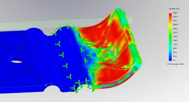
This is where simulation can become useful.
A Mold Flow analysis can help engineers understand whether the geometry is likely to create filling, packing, cooling, or warpage problems before steel is cut.
05 — Ribs and Bosses Were Designed Without Tooling in Mind
Ribs and bosses are essential features in many plastic products.
They provide:
- Structural stiffness
- Screw attachment
- Locating
- Assembly support
But they also create manufacturing considerations.
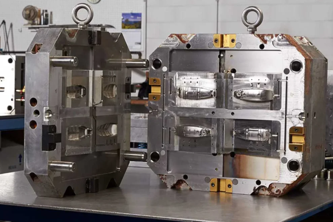
A deep boss may require a difficult core.
A thick rib can create sink marks.
A narrow gap may be difficult to machine or polish.
A boss positioned too close to another feature can create tooling or cooling problems.
The question should therefore not simply be:
“Can this feature be created in CAD?”
It should be:
“Can this feature be molded, cooled, ejected, inspected and maintained?”
06 — The Gate Has Nowhere Good to Go
Product designers naturally focus on the finished component.
Tooling engineers have another question:
Where does the plastic enter?
Gate location can influence:
- Filling
- Weld-line location
- Packing
- Shrinkage
- Warpage
- Cosmetic appearance
- Fiber orientation
- Cycle behavior
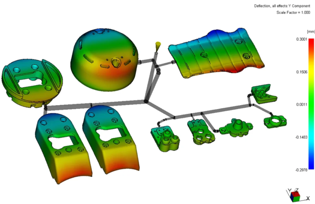
A CAD model may look excellent while leaving no practical gate location.
The gate may need to be placed on a cosmetic surface.
Or the flow length may become excessive.
Or a weld line may appear near a critical feature.
Sometimes the best solution is not simply changing the mold.
It may be changing the product geometry.
Gate strategy is often a product-engineering decision as much as a tooling decision.
07 — Ejection Was Treated as Someone Else’s Problem
A mold does not simply create a part.
It also has to release it.
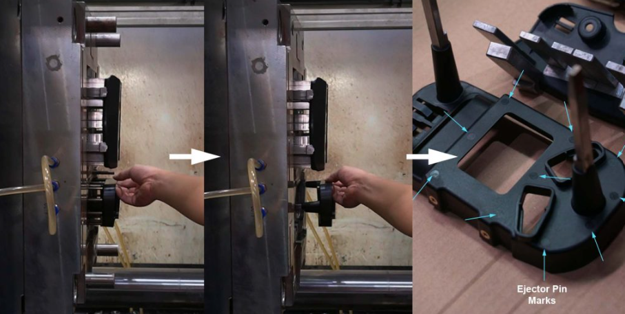
The tooling engineer therefore needs to understand:
How will the molded component leave the mold?
Ejection may involve:
- Ejector pins
- Sleeves
- Strippers
- Lifters
- Air assistance
- Mold opening sequence
The location and geometry of these systems can affect the part.
For example, an ejector pin may leave a mark on a visible surface.
A thin wall may not tolerate a high local ejection force.
A deep rib may make ejection difficult.
A cosmetic housing may have very limited areas where ejector marks are acceptable.
If the ejection strategy is discovered too late, the available options become much smaller.
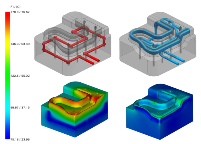
08 — Cooling Has Not Been Considered
Cooling is one of the most important—and often least visible—parts of injection molding.
A CAD model may contain beautiful external geometry.
But if the mold cannot cool the part effectively, production can still become difficult.
Uneven cooling can contribute to:
- Differential shrinkage
- Warpage
- Dimensional instability
- Longer cycle time
- Inconsistent production
This becomes particularly important for:
- Large housings
- Thick-and-thin sections
- Deep ribs
- Complex cores
- High-performance engineering plastics
A production-ready design therefore needs to consider not only how plastic flows into the cavity, but also how heat will leave the molded part.
09 — Critical Dimensions Are Not Connected to the Mold Strategy
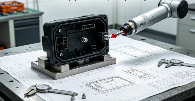
A drawing may specify a very tight tolerance.
For example:
±0.03 mm
But specifying the tolerance is only the beginning.
The engineering team should also understand:
- Where the dimension is created in the mold
- Whether it crosses the parting line
- Whether it depends on an insert
- How material shrinkage affects it
- How temperature affects it
- How the process will control it
- How it will be inspected
A critical dimension should therefore be connected to a manufacturing strategy.
Otherwise, the drawing may simply demand a result without defining a realistic path to achieve it.
A tolerance requirement without a manufacturing strategy is not a complete engineering decision.
10 — The Design Was Optimized for CAD, Not for Production
This is perhaps the biggest issue.
A CAD model can be optimized for:
- Appearance
- Packaging
- Assembly
- Function
- Rendering
- Simulation
But production requires another layer of thinking.
The design must work with:
Material
Mold
Machine
Process
Inspection
Assembly
Maintenance
Production volume
That does not mean every designer needs to become a tooling engineer.
It means the product development process needs manufacturing input early enough to influence the design.
From CAD-Ready to Production-Ready
There is an important difference between these two statements:
“The CAD model is finished.”
and:
“The design is ready for tooling.”
The first describes the status of the digital model.
The second describes the maturity of the engineering decision.
A production-ready injection molded design should answer questions such as:
How will the mold open?
Where is the parting line?
Where does the material enter?
How will the part cool?
How will it be ejected?
Where are the critical dimensions?
What happens to the material during molding?
How will the finished part be inspected and assembled?
If these questions have not been considered, the CAD model may be complete—but the product design is not necessarily production-ready.
The Engineering Takeaway
The purpose of DFM is not to make a designer’s job more difficult.
It is to move manufacturing problems to the earliest possible stage of the project.
A geometry change in CAD may take an hour.
A mold modification may take days.
A mold trial may take weeks.
A production change can affect thousands of parts.
That is why experienced engineering teams involve tooling and manufacturing expertise early.
A good CAD model defines the product.
A good DFM process helps define how that product becomes a repeatable manufactured part.
And that is the difference between a design that looks manufacturable and one that is actually ready for production.