


Insert molding a BLDC motor rotor is very different from molding a conventional plastic component.
The plastic is molded directly around a metal rotor assembly, magnet, shaft, or other functional insert. The molded polymer may provide insulation, positioning, protection, balancing, or structural retention.
That creates a difficult molding environment.
The insert itself can:
- Block normal air evacuation
- Create thin annular flow channels
- Produce unbalanced filling
- Trap air at the end of fill
- Increase local shear and pressure
- Introduce dimensional variation
For rotor overmolding, bubble-free molding is therefore not simply a material or machine-setting problem.
It is a combined problem involving:
Insert design + venting + gate design + mold temperature + injection pressure + holding pressure + material preparation + process control.
The objective is not merely to fill the cavity.
The objective is to fill the cavity completely while controlling air, pressure, temperature, and insert position throughout the molding cycle.
1. Engineering Problem: Why BLDC Rotor Overmolding Is Difficult
A BLDC rotor typically contains a combination of functional components such as:
- Steel rotor core
- Shaft
- Permanent magnets
- Magnet retaining structures
- Balancing features
- Electrical or magnetic isolation layers
During overmolding, molten resin must flow around these components while displaced air escapes from the cavity.
This creates several potential defects.
Typical defects include:
- Internal bubbles
- Voids
- Burn marks
- Short shots
- Flash
- Magnet displacement
- Shaft movement
- Uneven polymer thickness
- Parting-line leakage
- Excessive residual stress
For a rotor, these defects can become more serious than ordinary cosmetic defects.
An internal void may affect:
- Rotor balance
- Mechanical integrity
- Heat transfer
- Magnet retention
- Long-term reliability
A small bubble may therefore become a functional problem after thousands of operating hours.
2. Root Cause: Trapped Air Is Often a Mold Design Problem
A common reaction to bubbles is:
“Increase injection pressure.”
This is often the wrong first response.
If air has nowhere to escape, increasing injection pressure simply compresses the trapped air.
The result may be:
- Higher local temperature
- Burn marks
- Gas compression
- Internal voids
- Flash
- Greater molding stress
The fundamental question should instead be:
Where does the air go when the resin enters the cavity?
For rotor overmolding, the insert often creates a highly restricted flow environment.
Air may become trapped:
- Behind magnets
- Between the rotor and cavity wall
- Around the shaft
- At the end of an annular flow path
- Inside narrow pockets
- Near ribs or retaining features
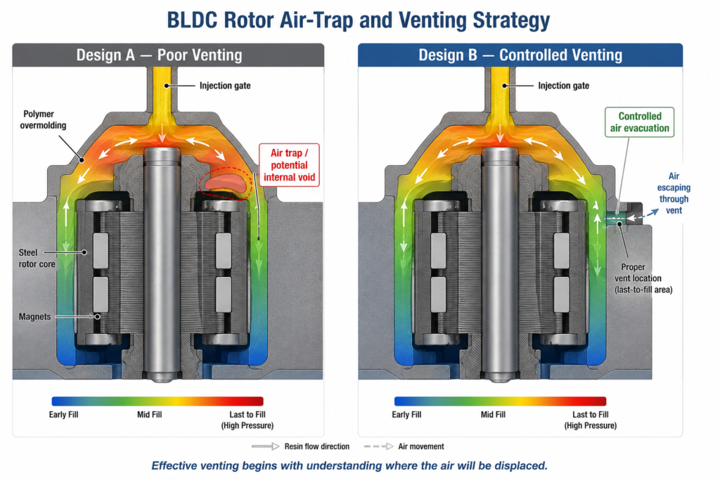
A good mold must provide a controlled escape path for this air.
3. Venting Design: The First Line of Defense Against Bubbles
Venting should be considered during mold design rather than added only after the first molding trial.
For rotor insert molding, conventional parting-line vents may not be sufficient.
The venting strategy may need to include:
- Parting-line vents
- End-of-fill vents
- Insert interface vents
- Ejector-assisted venting
- Dedicated vent grooves
- Vacuum-assisted venting for particularly difficult applications
The exact design depends on the resin, insert geometry, filling pattern, and required cosmetic or functional performance.
Vent Location Matters More Than Vent Quantity
Adding more vents does not automatically solve an air-trap problem.
The important question is:
Are the vents located where the final flow fronts actually arrive?
This is where Mold Flow Analysis can provide significant value.
A simulation can predict:
- Fill sequence
- Last-to-fill areas
- Potential air traps
- Knit-line locations
- Pressure distribution
The venting strategy can then be designed around the actual filling behavior.
4. Practical Venting Guidelines
Vent dimensions must be selected according to the specific resin and molding process.
There is no universal vent depth suitable for every material.
As an engineering starting point, many thermoplastics use vent depths in the range of approximately:
0.02–0.05 mm
with the vent land and downstream vent channel designed to allow air to escape without allowing excessive resin flash.
For highly sensitive applications, the actual value should be validated using:
- Resin supplier recommendations
- Mold trials
- Flash evaluation
- Burn-mark evaluation
- Pressure monitoring
The important principle is:
A vent must be deep enough to release gas but controlled enough to prevent resin leakage.
5. Injection Pressure Control
Injection pressure is another critical variable.
However, pressure should be controlled as part of a complete filling strategy.
If the initial injection pressure is too low:
- Filling may stop
- Thin areas may freeze
- Knit-line bonding may deteriorate
- Short shots may occur
If pressure is too high:
- Flash may develop
- Insert movement may occur
- Mold stress increases
- Residual stress can increase
- Trapped gas may become highly compressed
The target is not:
“Maximum pressure.”
The target is:
“The lowest stable pressure that reliably fills the cavity.”
6. Injection Speed and Pressure Must Be Considered Together
Injection speed affects the way resin fills the rotor cavity.
A very slow filling speed can allow the material to cool excessively before reaching the final filling region.
A very aggressive filling speed can:
- Increase shear heating
- Compress trapped air rapidly
- Increase flash risk
- Increase insert movement
For this reason, a staged injection profile is often more useful than a single fixed injection speed.
A typical development strategy is:
Stage 1 — Controlled Filling
Use a moderate initial injection speed to establish stable flow.
Stage 2 — Main Filling
Increase speed where necessary to maintain resin temperature and filling stability.
Stage 3 — End-of-Fill Control
Reduce or carefully control the injection behavior as the cavity approaches full.
This final stage is particularly important when the rotor has a narrow annular flow path.
7. Holding Pressure Is Not a Solution for Trapped Air
Holding pressure is intended to compensate for material shrinkage after the cavity has been filled.
It is not intended to solve an air-trapping problem.
If a cavity contains trapped air, increasing holding pressure may simply increase the pressure acting on the trapped gas.
The correct sequence is:
Good filling → Effective venting → Stable transfer → Controlled packing
not:
Poor venting → Increase pressure → Hope the bubbles disappear
8. Material Preparation Is Part of Bubble Prevention
Not all bubbles originate from trapped cavity air.
Moisture in the resin can generate gas during molding.
This is particularly important for hygroscopic engineering plastics such as:
- PA
- PC
- PBT
- Certain TPU and other moisture-sensitive grades
Moisture can lead to:
- Splay
- Voids
- Surface defects
- Reduced mechanical properties
- Hydrolytic degradation
Material drying must therefore be controlled according to the specific resin manufacturer’s drying requirements.
A good SOP should record:
- Resin lot
- Drying temperature
- Drying time
- Dryer dew point
- Material exposure time
- Time between drying and molding
9. Insert Preparation Is Equally Important
The rotor insert itself can introduce contamination or trapped gas.
Before molding, inspect:
- Magnet position
- Shaft concentricity
- Rotor surface cleanliness
- Oil or grease contamination
- Metal particles
- Protective coatings
- Insert dimensions
Any contamination between the insert and polymer can become a source of:
- Poor adhesion
- Voids
- Delamination
- Gas generation
- Dimensional instability
For production applications, insert cleanliness should be treated as a controlled process parameter—not an operator preference.
10. Mold Temperature and Resin Temperature
Temperature has a direct effect on flow.
A colder mold can cause:
- Premature freezing
- Higher injection pressure
- Poor weld-line bonding
- Short shots
A hotter mold can improve flow and surface replication but may also:
- Increase cycle time
- Increase thermal exposure
- Affect dimensional stability
The correct window depends on the resin grade.
For precision rotor overmolding, it is better to establish a controlled process window than to select a single temperature based only on general material tables.
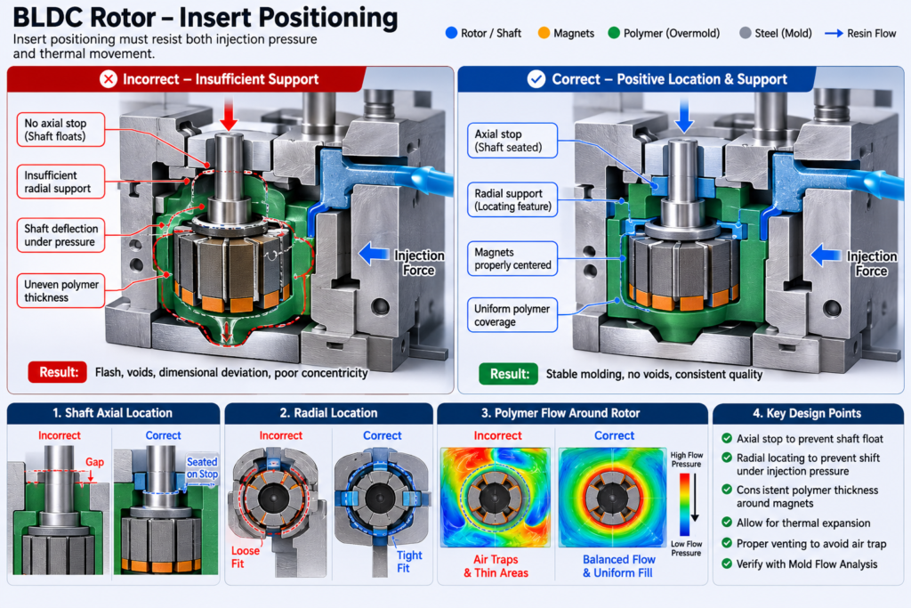
11. Insert Positioning and Clamping
A rotor is not a passive insert.
It contains functional geometry that may move if the molding forces are not properly controlled.
Injection pressure can generate forces that act on:
- Shaft
- Magnets
- Rotor laminations
- Retaining components
If the insert is not adequately supported, molding can produce:
- Shaft eccentricity
- Magnet displacement
- Uneven polymer thickness
- Rotor imbalance
This is particularly important for high-speed BLDC motors.
The mold should therefore control the insert through appropriate:
- Locating features
- Support surfaces
- Clamping points
- Core pins
- Bushings
- Axial positioning features
12. Gate Design for Rotor Overmolding
Gate location has a major influence on:
- Flow symmetry
- Pressure distribution
- Insert movement
- Weld-line location
- Air-trap position
- Polymer thickness
For rotational components, balanced filling is particularly important.
An asymmetric filling pattern may produce uneven pressure around the rotor.
This can contribute to:
- Insert displacement
- Uneven encapsulation
- Dimensional variation
For critical rotor applications, gate design should therefore be evaluated together with Mold Flow Analysis.
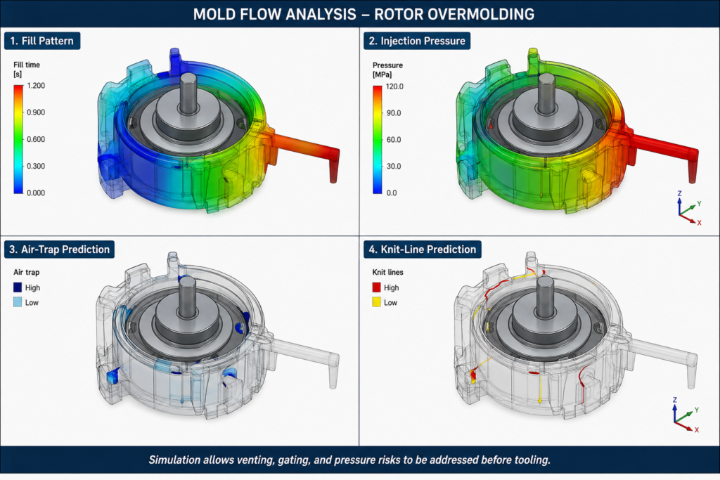
13. Mold Flow Analysis for Zero-Bubble Development
For demanding rotor overmolding applications, Mold Flow Analysis can be used to predict:
- Fill sequence
- Pressure
- Flow balance
- Air traps
- Knit lines
- Last-to-fill regions
The analysis should answer several practical questions:
Where will the resin arrive last?
Where will the air accumulate?
Is the pressure balanced around the rotor?
Could the flow force move the insert?
Will the knit line occur in a functional region?
The simulation should then drive the mold design.
14. Zero-Bubble SOP
A zero-bubble target should not depend on one machine parameter.
It should be managed through a controlled process.
Step 1 — Incoming Material Control
Verify:
- Correct resin grade
- Resin lot
- Moisture condition
- Storage condition
Step 2 — Resin Drying
Set drying conditions according to the resin supplier’s specification.
Record:
- Temperature
- Time
- Dew point
- Exposure time
Step 3 — Insert Inspection
Verify:
- Shaft position
- Magnet position
- Rotor dimensions
- Surface cleanliness
- Insert concentricity
Step 4 — Mold Preparation
Inspect:
- Vent cleanliness
- Vent dimensions
- Gate condition
- Cooling system
- Insert locating features
Blocked vents should be treated as a process abnormality.
Step 5 — Controlled Filling
Establish:
- Injection speed profile
- Transfer position
- Injection pressure limit
- Mold temperature
Avoid simply maximizing injection speed.
Step 6 — Controlled Packing
Set:
- Holding pressure
- Holding time
- Transfer point
The objective is dimensional stability—not forcing more material into a poorly vented cavity.
Step 7 — Part Inspection
For critical rotor applications, visual inspection alone may not be sufficient.
Depending on the application, inspection may include:
- Cross-section analysis
- X-ray or CT inspection
- Weight measurement
- Dimensional inspection
- Concentricity measurement
- Dynamic balancing
Step 8 — Process Monitoring
Record critical parameters for each production run.
At minimum:
- Resin lot
- Drying condition
- Mold temperature
- Injection pressure
- Injection time
- Holding pressure
- Cycle time
- Part weight
This creates traceability when defects appear later.
DFM Quick Review Checklist: BLDC Rotor Overmolding
- Is the resin grade and drying requirement confirmed?
- Are the predicted last-to-fill areas properly vented?
- Is the gate strategy balanced around the rotor?
- Is the insert positively located and supported?
- Is injection pressure controlled within a validated process window?
- Have air traps and knit lines been reviewed through simulation or trials?
- Is internal void detection defined for critical parts?
Final Thoughts
Bubble-free BLDC rotor overmolding is not achieved by simply increasing injection pressure.
The real solution is to control the entire molding system:
Material → Insert → Gate → Flow → Venting → Pressure → Cooling → Inspection
A well-designed vent cannot compensate for poor material drying.
A high-quality resin cannot compensate for an incorrect gate.
A high injection pressure cannot compensate for trapped air.
And a good mold cannot compensate for uncontrolled insert positioning.
For demanding BLDC motor applications, the most reliable approach is to treat zero-bubble molding as a process-control problem from the beginning of tooling design.
The objective is not simply to produce a rotor that looks good after molding.
It is to produce a rotor with:
- Consistent encapsulation
- Controlled dimensions
- Stable insert position
- Minimal internal voids
- Reliable mechanical integrity
- Repeatable production performance
That is where precision insert molding becomes a true engineering discipline rather than simply an injection molding operation.